Team Joker - Robot Construction
On this page ...
Design
Specifications
Transmission
Power
Weapons
Team Joker - The Design
Overall
Joker might not be destructive like many of our competitors but if we were to be able to push our foes down the pit, we would be happy.
We have a four wheel drive machine, steering is by having the drive wheels moving at different speeds (Differential steering). The weapon is an electric lift. This also acts as a self righting mechanism although the robot will run both ways up. The design is largely symmetrical in all three planes and does not have any end dedicated as the front or bottom. Armour is 6mm aluminium chequerplate internally braced and can support the wheel of a car.
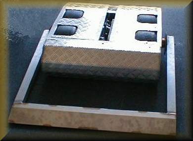
We learnt a great deal about how not to build a robot with our first design called Pugno (pictured above). This machine, although very strong was vastly overweight.
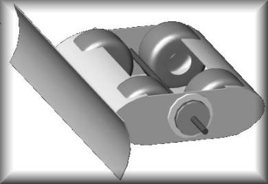
This picture shows one of our newer robot designs as rendered by our CAD program - a necessary tool in the development of modern complex machines.
The Body
The frame made out of square section aluminium tube was discarded in favour of a monocoque hull. This is because
- The frame we used originally was too bulky and got in the way of construction. An empty monocoque hull gives greater freedom to place components, and liberates space to swing the spanners.
- A monocoque is lighter so a greater thickness of metal can be used - the metal is put where it is needed - on the outside.
- Curved ends can be used if we opt for a monocoque chassis. The ends take the most impact and 'egg shaped' ends are stronger than flat ends.
- The ends wrap around the electric motors. This further strengthens the ends. Good thermal contact between motors and the hull dissipates heat.
Top of Page
Team Joker - Specifications
Overall Specification
- Hull mass 19k
- Length 750 mm
- Width 750 mm
- Hull depth 200 mm
- Hull material 6mm aluminium chequerplate welded inside and out
Weights - Totalling approx. 95 kg
| Hull | 19 kg | Wheels | 8 kg | |
| Left Motor | 8.5 kg | Axles | 6 kg | |
| Right Motor | 8.5 kg | Chain | 6 kg | |
| Lift Motor | 7 kg | Misc | 2 kg | |
| 6 Batteries | 16 kg | Bearings | 2 kg | |
| Controllers | 1 kg | Weapon | 10 kg |
Drive Motors
Manufacturer : NECO
Frames : PM714C
Body Diameter : 122mm
Body Length : 268mm
Armature Resistance : 0.11 ohms (cold) 8.7 ohms (Hot)
Armature Inductance : 3.2 milli Henries
Max short-circuit current : 250 Amps
Max current before motor is demagnetised : 160 Amps
Max power delivery per motor for 20 seconds : 2kW
Max instantaneous power delivery per motor for 1 second : 6kw
Battery Current drawn to climb 1:1 hill : 40 Amps
Controlled RMS voltage needed for motors to climb 1:1 hill : 5v
Radio Frequencies Available
Most competitions require robots to operate on the 40MHz frequency. In Britain, boats, land machines and aircraft may use these frequencies. In this country the available frequencies and channels are -
| Frequency | Channel No | Frequency | Channel No | |
| 40.665 | Channel 50 | 40.815 | Channel 81 | |
| 40.675 | Channel 51 | 40.825 | Channel 82 | |
| 40.685 | Channel 52 | 40.835 | Channel 83 | |
| 40.695 | Channel 53 | 40.845 | ||
| 40.705 | 40.855 | |||
| 40.715 | Channel 54 | 40.865 | Channel 84 | |
| 40.725 | Channel 55 | 40.875 | Channel 85 | |
| 40.735 | Channel 56 | 40.885 | Channel 86 | |
| 40.745 | 40.895 | |||
| 40.755 | Channel 57 | 40.905 | ||
| 40.765 | 40.915 | Channel 87 | ||
| 40.775 | Channel 58 | 40.925 | Channel 88 | |
| 40.785 | Channel 59 | 40.935 | Channel 89 | |
| 40.795 | 40.945 | |||
| 40.805 | 40.955 |
Channels 60 to 80 belong to the 35MHz band (Model Aeroplanes only)
Transmitter
We are presently using a modified Futaba Field Force 6 system. This set is designed for aircraft use but was supplied with a 40 MHz module. As standard, engine speed does not centre. For controling the speed of the robot we now use the left joystick fitted with a self-centring device but no friction mechanism. This means that the driver can release the sticks and the robot comes to rest.
The transmitter has both pulse coded and pulse positioning modulation selectable from the liquid crystal display. Individual models can be stored in the transmitters memory. This is useful to us since we have several models (ships, planes and cars) to control and this makes setting up easier. We nearly lost a radio controlled buggy on an aerodrome when it went out of range. At the time we were using Pulse Positioning Modulation and the buggy continued with the last known command. Clearly this could be dangerous with a 100kg robot. Pulse Coded Modulation is easily set up to immobilise the model (or send it in a circle) if the signal is lost.
Our Vantec speed controller will default to 'no power to the motors' when there is no signal. This will happen if we were using a PM receiver and the signal was lost. When a PCM receiver is used, then defaults must be set up. This is because the robot will continue with the last known signal should contact be lost. The defaults if programed into the transmitter are passed to the receiver every minute and tell the receiver what to do if the signal is lost. Should the signal fail then after 300 milliseconds, the receiver will carry out the default instructions and bring the robot to a halt.
The reason for our concern at the loss of signal is simple - the aerial might get bent or snapped off during the event! These precautions will ensure the robot comes safely to rest, without injuring bystanders or damaging itself further, until the aerial can be repaired.
Materials
Materials required for robot construction should be strong enough to survive a number of bouts, light enough to carry, easily machined and welded for construction and, above all, affordable. Aluminium chequer-plate was used for the hull of Joker
Material Strength can be expressed as...
| Elasticity | The sample springs back to the original shape |
| Ductility | The sample does not break easily when stretched though it deforms |
| Resilience | Elastic but little energy is lost when it springs back |
| Shear Strength | a measure of strength when layers of the material slide over each other |
| Tensile Strength | a measure of strength when the sample is pulled |
| Compressive Strength | a measure of strength when the sample is pushed |
| Wear resistance | the quality of a surface not to wear away |
If a sample is stretched, the force on the sample increases (the strain) and the sample elongates (becomes stressed). Up to a point most materials initially show a linear relationship between stress and strain (Hooker's Law) and, up to that point, releasing the force results in the sample regaining its original dimensions. The molecules of the sample do not change the chemical bonds between adjacent molecules.
When the forces are high, the bonds break and reform, the sample behaves as a plastic and the sample will suffer a permanent change of shape. The sample may then become weaker because the new bonds will be fewer and the sample becomes thinner where a neck forms.
In some materials however, the sample may become stronger. This is usually because the shape of the molecules alters so that stronger bonds can form, the metal becomes crystalline or the molecules themselves line up like fibres in a rope. Copper is an example of this. It may start off as a malleable metal. Bending it or stretching it will strengthen it. If it is stretched, the metal where it forms a neck becomes stronger and prevents further necking. This means that the metal may be drawn into wires and will resist breaking if the sample is repeatedly flexed and straightened. Heating the metal will soften it again. Such materials are said to be 'ductile'
Some metals are too hard to machine unless they are heated first. Rough treatment may restore their hardness. A blacksmith needs to constantly reheat a horseshoe to soften it so that it can be worked to the correct shape. Banging and quenching the material strengthens it. This is due to crystals forming in the metal, which strengthen it. (stones in concrete act the same way and hamper the propagation of cracks)
Large areas of crystalline substance are brittle and decrease the strength of the material. This happens in metal fatigue. Low temperatures can also fatigue a metal. Tin, for example turns into a powdery form at prolonged low temperatures (Tin disease). The hull of the Titanic may not have ruptured if the water was warm, but then there would have been no icebergs!
The elements of metals are usually alloyed with other substances, usually other metals, to alter their crystalline structure and make the resulting alloy stronger. Steel for example, is a mixture of the elements iron and carbon.
Tensile strength of some materials (MPa)
Also yield strength (MPa) and elongation (%)
| Material | Treatment | Tensile | Yield | Elong |
| 440C AISI stainless steel | annealed | 760 | 480 | 13% |
| 440C AISI stainless steel * | hardened at 330C | 1970 | 1900 | 2% |
| 5160 I-SAE alloy steel | tempered at 200C | 2200 | 1790 | 4% |
| Titanium Alloy # | Oxygen annealed at -225C | 1580 | 1420 | 15% |
| Aluminium Alloy 6061 T6 ~ | Solution heat treat & aged | 310 | 275 | 12% |
*Stainless steel was used for the weapon of Joker. It is not easily cut by House Robots and can be ground into a sharp blade.
# Titanium, although light, is springy and not suitable for rigid structures. It is more difficult to weld than aluminium.
~ Aluminium is considerably cheaper than Titanium and lighter (RD 2.7 vs 4.5) and is easier to weld. This is why we used aluminium alloy 6mm tread plate for the hull of Joker
For info...
Stainless Steel contains 1.07% Carbon, 17% Chromium and 1% Manganese.
Alloy Steel contains 0.60% Carbon, 0.80% Chromium and 0.88% Manganese.
Surface Treatments
Wear resistance, and to a smaller extent, the strength of a structure is a result of the surface treatment given to the object for example -
Bead blasting, Anodizing, Precipitation hardening, Work hardening, Case hardening, Cyaniding, Carbonizing, Nitriding, Carbonitriding, Flame hardening, Induction hardening
The chosen surface treatment must, of course, be suitable for the alloy in question.
We would have bead blasted and then anodized the aluminium hull of Joker if funds had permitted. This would have endowed the surface with colour as well as toughening it.
THE WEAPON COMPONENTS
The Geared Lift Motor
We used a Parvalux PM 50 LIS (in line multi-spur D.C. totally enclosed IP 54
permanent magnet motor. This is rated at 280 Watts for 15 minutes. It lacks the internal fan of the PM60 which is rated at 345 Watts.
The motor will only need to be operated for a few seconds during a bout so is driven well over its rated power. At 24 volts the motor turns at 3000 rpm, the output shaft turns at 27 rpm and has a rated torque of 81 Nm. It shares the same gear train as the PM60, which is rated at 100 Nm. At twice the voltage it will turn at 54 rpm.
The motor was modified thus -
- The oil was removed from the gearbox and the gears lightly greased.
- The output shaft was reduced in length and modified to take a 7-tooth pinion
- The box was re-assembled to put the output shaft near the top
- Flat countersunk screws were used upon reassembly to save space
- Suppressor capacitors were soldered across the brushes
- The brush cover screw was replaced with a countersunk item to save space
- The motor body was covered with insulating tape to prevent short circuits
- A spacer was fitted to the mounting base to give clearance to the speed controller
- The suppressing choke was dispensed with
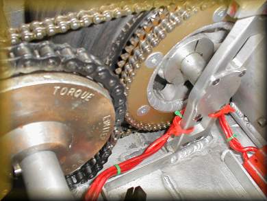
The Torque Limiter
Joker is easily flipped due to its high ride height of 10 mm. This is of no great consequence since it runs both sides up and can turn itself over using its lifter.
The weapon sticks out some distance and could exercise some leverage on the hull and damage it. This is reduced by incorporating a Cross & Morse Torque limiter model 500M2. This has a maximum rated torque of 57 kg at 1 metre. This can obviously be tightened up further if needed. In practice the level of torque is perfectly adequate because -
- Our favourite weapon is only about 860 mm in length
- We would turn ourselves over if the force exceeded 30 kg at 1 metre
- We only need to lift one end of our opponent so the force needed would be 50 kg
- We could lift 100 kg if the load was centred on our weapon.
The torque limiter has been modified by -
- Putting it in a lathe and removing all excess metal
- Replacing the hexagonal setscrews with socket grub screws to save space and weight
- Bored out the centre to 25 mm
- Broached a key way into the centre hole
- The clutch was fitted with a 35-tooth 1/2 inch pitch plain plate sprocket
Gearing
The lift motor is geared 5:1 through a standard chain. This means that the shaft will have a torque of 500 Nm or 50 kg at 1 metre. Exceeding the rating of the motor by, say 100% will mean that another robot could easily be lifted if Joker was glued to the arena floor. In practice, the weapon is pushed down and the front of Joker is lifted. The weapon is slid under our opponent and then raised. This will lever the weapon and our opponent off the floor. They will lose traction and the result is a victory (in theory!).
The motors were designed to run on a 24 volt supply. They will obviously run around twice as fast on 55 volts. The gearing will reduce the weapon shaft to about 10 rpm or one revolution every 6 seconds. This is a little fast in practice and when funds are available, a speed controller will be fitted to replace our relay and resistor circuit we use to control the lift at present.
The Shaft and lift
This is under construction. Our aluminium shaft and stainless steel demountable unit will be modified to take advantage of the rule changes. Interchangeable weapons are now no longer permitted for Robot Wars so a one-piece unit will be fitted. This will be stronger.
Top of PageTeam Joker - Transmission
The motors
These are bespoke units and are very heavy. They are lightened a little by removing the mounting feet. The curvature of the body, clamps within the shell hold the motors (and further strengthen the body) and the original bolt holes are used to mount the motors even more securely. Conductive paste now improves heat conduction to the hull and matt black paint (on surfaces which get hot or which face hot surfaces) improves radiation.
To convert electrical energy to mechanical energy efficiently, large magnetic fields must be used. Our motors are large. These motors are so efficient that they will spin with considerable torque even on an AA battery. We expect that the improved efficiency would allow us to save on battery mass.
Note that the so called 'permanant' magnets will lose their strength if subject to trauma or if the magnetic field is not concentrated through the comutator. To minimise loss of magnetism, the motors are never dismantled so the commutator acts as a magnet "keeper". Thus, the motors were specified with tapers and keys to suit our pinion gears and will not need to be taken apart after manufacture. Over time, and with heavy (ab)use the magnets will start to weaken which will cause the motors to run faster.
For the technical minded folks - loss of magnetism will cause a corresponding loss of back-EMF when electric motors are running. To produce the same back-EMF, motors with weakened magnets will have to run faster. Our 'Joker' will have a higher maximum speed as she ages.
To reduce inertia the motors are quite long compared to their diameter.
Pugno had the motors mounted in line at one end of the machine. This resulted in a wide configeration. 'Joker' has the motors mounted at either end in a symetrical configeration. The hull is much narrower
Motor Specifications
- Nominal operating voltage 36V
- Weight 2x 11kg
- Will run equally well both directions (zero timed)
- Rare earth permanant magnets, the mounting improved by filling the voids between the magnets with epoxy resin.
- Fully enclosed design to prevent the ingress of swarf
- Maximum usable torque - 5Nm at 6V across the terminals.
- Maximum efficiency - 80% at 2350 rpm
- Maximum estimated current - 160A (limited by the magnets being demagnetised)
- Estimated maximum power 2kW for 2s (4kW total)
The Axles
Pugno had axles which went through the width of the machine. This added strength but reduced the usable space considerably. This was ditched in favour of stub axles bolted to the monocoque and also onto pillars within the machine which further strengthened the structure.
Axle Specification
- Axle lengths - 200mm
- Diameter - 25mm
- Material - aluminium rod, bored out to reduce mass
The Wheels
Kart components are retained. Weight has been saved by welding the pairs of wheel and sprocket carriers together and then lathing off surplus metal. The carriers are modified to carry two sprockets. The weight of nuts has been saved by Helicoiling the mounting holes and using short bolts. As a bonus, the carriers now do not need not be tightened up to prevent them slipping on the axles due to motor torque since they are now welded together.
The transmission chains are now located by the wheels rather than in a central chest as previously.
The tyres can be foam filled to prevent them being disabled due to punctures.
Wheel Specification
- 10 inch front kart wheels and very sticky tyres
- Grip improved by wiping the tyres with grip improver
- Motor Sprocket teeth 9
- Wheel Sprocket teeth 66
- Gold kart chain
- Primary chains from motor and secondary chains joining the wheels on each side together.
- Speed at 2350 RPM = 9.5 mph
Team Joker - Power & Electronics
Batteries
We now have space within the monocoque to place the batteries together as a block. Advantages are -
- The batteries are easier to mount
- They are taped together and easier to remove as a block
- Wiring is simpler and more compact. Brass bus bars are used to connect the batteries together
Battery Specification -
- 6 x Red top 8Ah 12V batteries
- 42A for 5 minutes
- 300A maximum
- Dimensions 138 x 86 x 101 mm
- M4 bolt terminal
The batteries can be configured to produce 12, 24, 36, 48, 60 or 72 volts depending of the number connected in series. we use 2 strings of three batteries
Wiring
There is no advantage in using wiring having a larger cross section than the smallest in the circuit or the melting point of the insulation higher than the melting point of solder. The wiring has been down specified in Joker. This saves weight, makes soldering easier and makes the routing of the wires easier.
Wiring Specification -
- Area, 8mm sqare multistrand quality loudspeaker wire to each motor
- two wires paralleled from the batteries to the controller
- 2 X 80A large spade type car fuses
Electronics
This had been reliable but unexpectedly broke down in July 2002 in a rather dramatic manner. 160A fuses blew repeatedly - quite spectacular!. Our speed controllers needed a complete rebuild as the MOSFET transistors had disintegrated. At that juncture we decided to rename our mischievous creation 'Joker'.
Electronics Specification -
- Vantec RDFR47E controller
- 9-60V operation
Team Joker - Weapons
Our original design was a lift powered by two Parvarlux geared motors mounted at one end and driving external chains to plate wheels welded to the weapon. This was very powerful but also heavy and vulnerable to impact damage.
Clearly this was in urgent need of a redesign.
This latest electrical lift is powered by a single geared Parvarlux motor via a heavyweight chain to a torque limiting clutch (set to 50kg at 1 metre) mounted on a transverse axle. This axle runs between the wheels. Large aluminium plates bolted to the sides spread the load and support the weapon bearings. Interchangeable weapons mount onto this axle.
The weapon provides us with a self-righting mechanism. However, since the robot is largely symmetrical in three planes, i.e. it works just as well "upside down" or running "backwards".
Weapon Specification -
- Lift motor 7kg
- Lift speed 30 rpm at 36V
- Torque of lift mechanism 500Nm at 36V protected by clutch
- Electric lift about 100kg capacity depending on length of weapon
- Length about 500mm
- A replaceable component
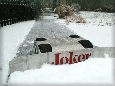
This plough was originally designed for football.
It came in handy in the recent snowfalls.
The side bearings are each threaded to receive a bolt which easily allows quick replacement of the weapon during bouts. However, the entire transverse shaft may also be removed using one of two methods...
- A joining muff on the shaft can be released to allow this component to be removed from either side.
- Vertical slots in the side allow the shaft to be removed as one unit. The transmission chains must be parted to facilitate this.
Next Chapter :
Joker - Combat History etc.